


A high gain DC-DC converter based on switched capacitor and coupled inductor voltage multiplier unit
-
摘要:
针对激光无线能量传输系统中光伏电池阵列输出电压低,需要高增益变换器进行升压变换的问题,提出一种基于开关电容与三绕组耦合电感倍压单元的新型高增益直流变换器。该变换器将电荷泵电容、箝位电容、倍压电容与三绕组耦合电感各绕组相配合,使电压均匀分配,提高变换器电压增益的同时使功率器件的电压应力显著下降。开关电容中的箝位电容实现了对功率开关管断开瞬间耦合电感漏感能量的缓冲吸收,避免尖峰电压产生的同时,实现了功率开关管的零电流导通,有助于变换器效率的提升。通过模拟仿真和实验对所提变换器工作原理和性能进行了分析验证。
-
关键词:
- 激光无线电能传输技术 /
- 高增益直流变换器 /
- 耦合电感 /
- 开关电容 /
- 倍压单元
Abstract:This paper addresses the low port voltage of the photovoltaic array in laser wireless power technology, which requires high-gain DC-DC converters for voltage boosting. The first is a new high-gain DC-DC converter that uses a triple-winding coupled inductor voltage multiplier unit with switching capacitors. By coordinating the windings of the triple-winding coupled inductor with the charge pump, clamping, and voltage multiplier capacitors, the voltage gain is uniformly distributed among the boost units, greatly increasing the converter's voltage gain and lowering the voltage stress on power devices. In addition, the clamping capacitor in the switched capacitor absorbs the energy stored in the coupled inductor's leakage inductance when the power switching device is turned off, preventing the formation of a voltage spike while achieving zero-current turn-on of the power switching device, both of which helps to improve the efficiency of the converter. Then, the working principle and steady-state performance of the proposed converter are analyzed in detail. Ultimately, a prototype and simulation model are developed based on the suggested concept, and simulation and experimentation are used to confirm that the performance analysis and working principle of the suggested converter are accurate.
-
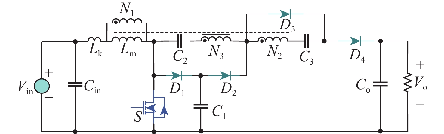
图 1 本文高增益直流变换器电路拓扑
Figure 1. Circuit topology of the proposed high gain DC-DC converter
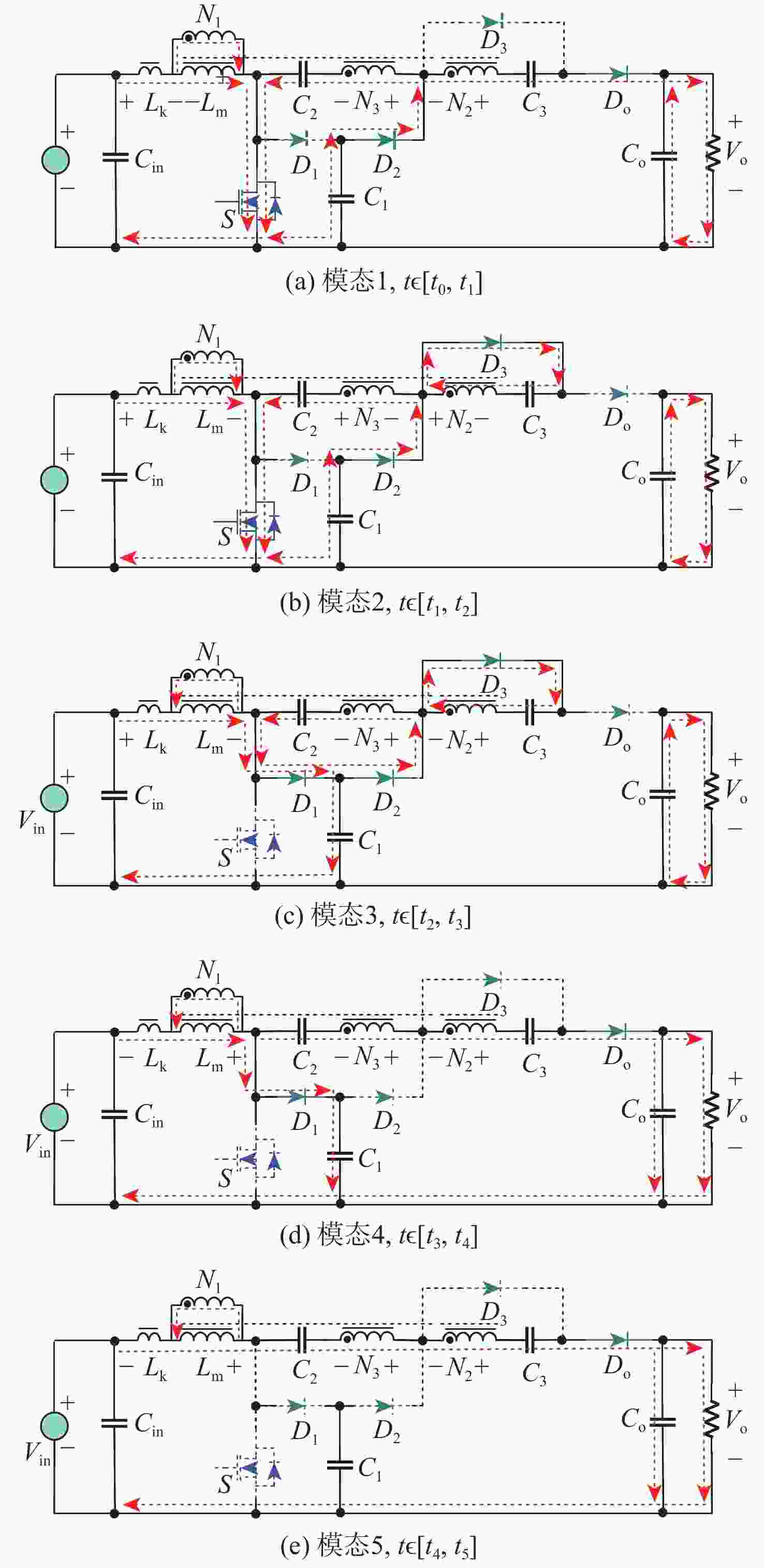
图 2 考虑漏感时变换器CCM下工作模态
Figure 2. Operating mode of converter in CCM under leakage inductance state
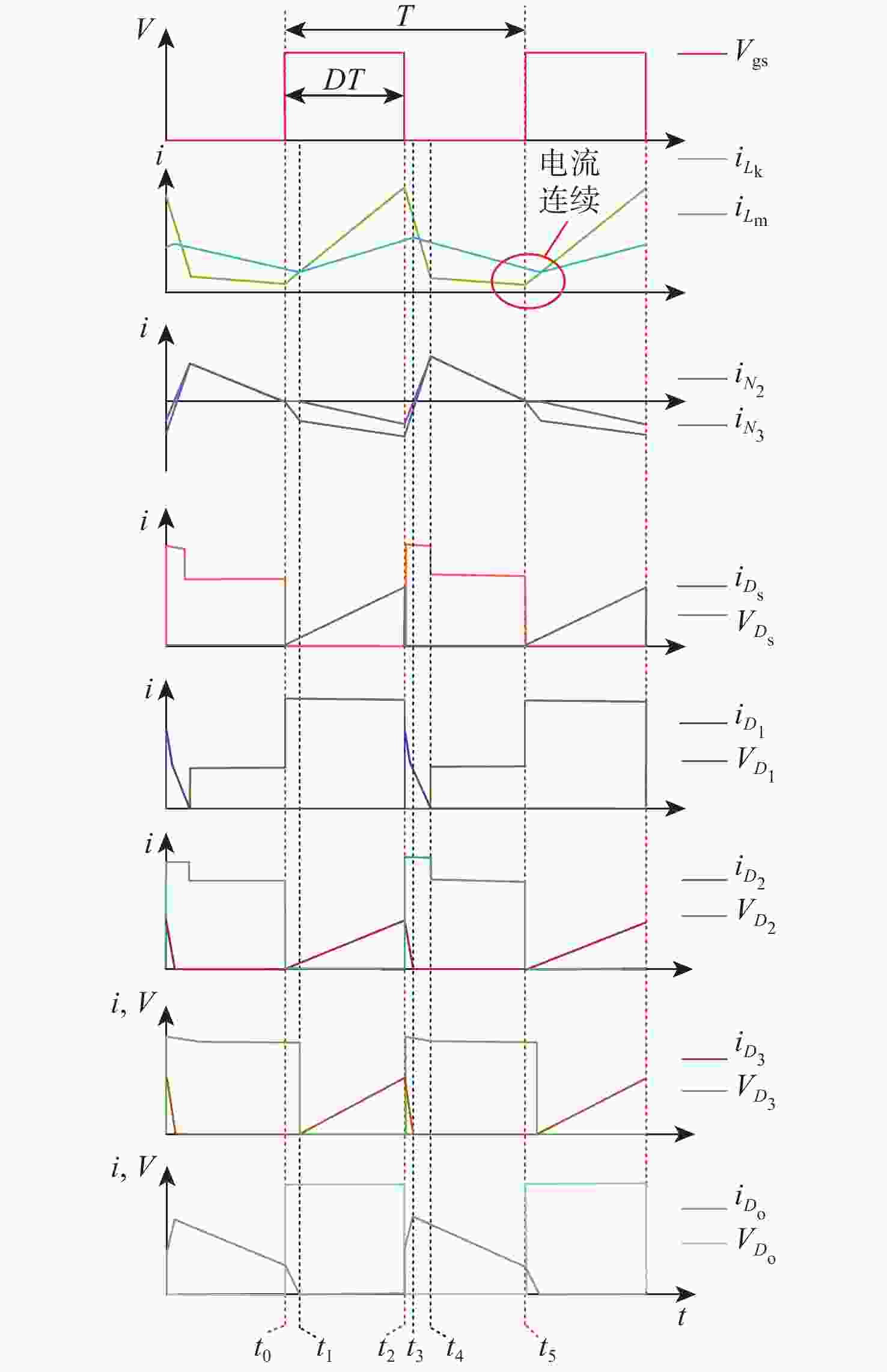
图 3 本文变换器CCM工作模式下工作波形
Figure 3. Main operating waveforms of the proposed converter in CCM mode

图 4 考虑漏感时本文变换器DCM模式下工作模态
Figure 4. Operating mode of the converter in DCM mode under leakage inductance state

图 5 本文变换器DCM工作模式下工作波形
Figure 5. Main operating waveforms of the proposed converter in DCM mode

图 6 本文变换器不同耦合系数k下电压增益
Figure 6. Voltage gain of the proposed converter with different coupling coefficient k
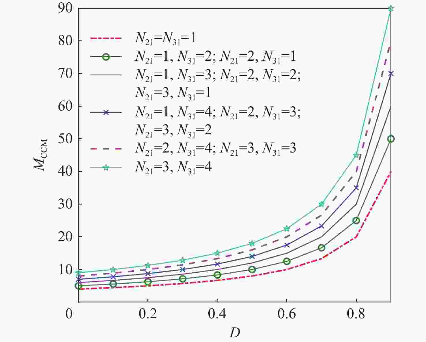
图 7 本文变换器CCM模式下不同线圈匝比下电压增益
Figure 7. Voltage gain of the proposed converter with different coil turn ratio in CCM
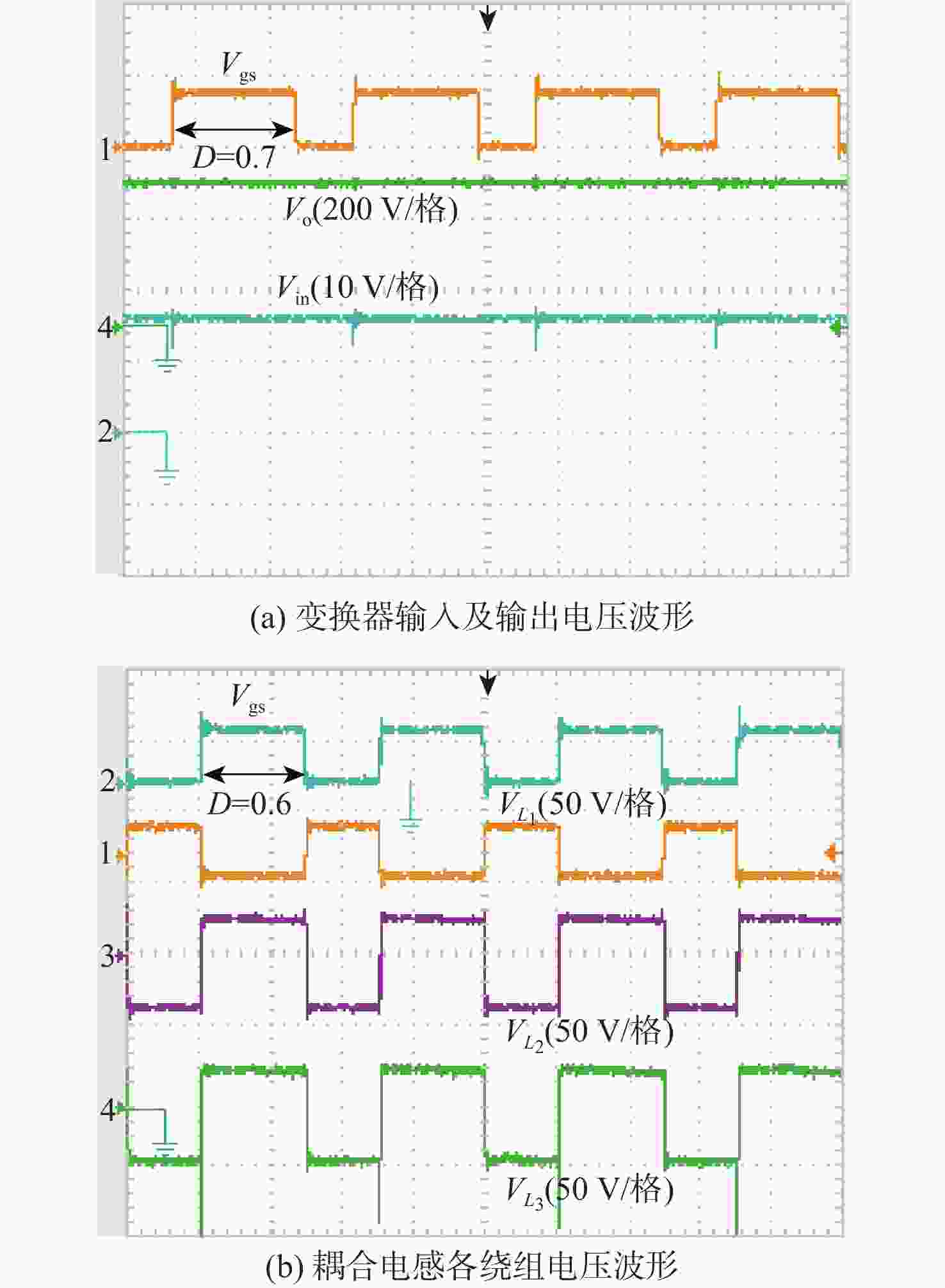
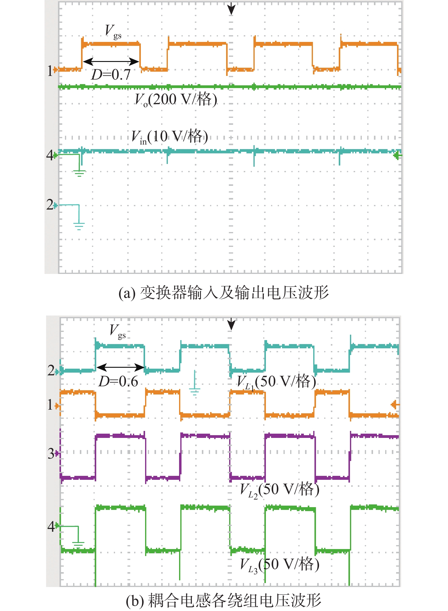
图 13 本文变换器样机实验波形
Figure 13. Experimental waveforms of the proposed converter prototype
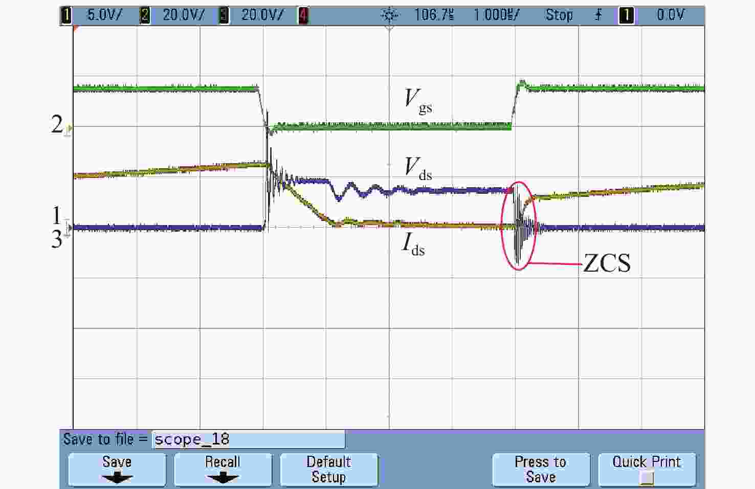
图 15 开关管S零电流导通波形
Figure 15. Experimental waveforms of switch S on zero current conduction
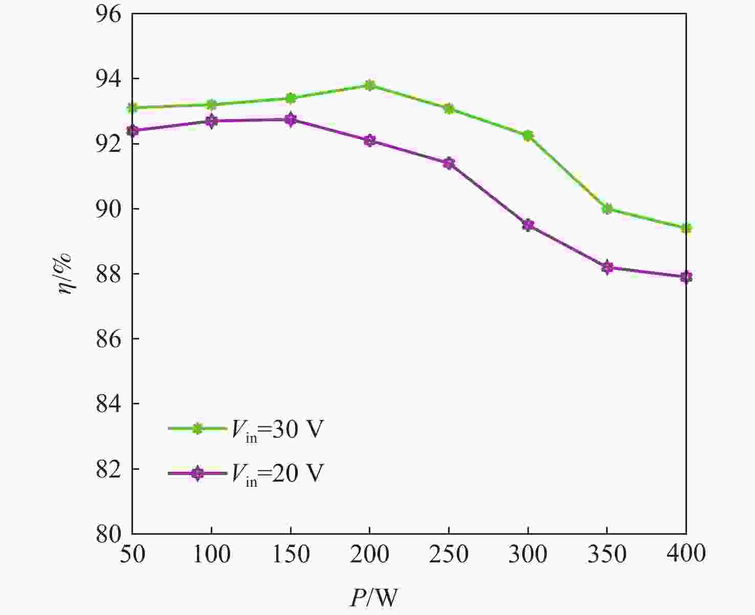
图 16 不同电压和功率等级下本文变换器效率
Figure 16. Efficiency of the converter at different voltage and power levels
表 1 本文三绕组耦合电感变换器仿真参数
Table 1. Simulation parameters of the proposed three-winding coupled inductor converter
参数 值 输入电压Vin/V 20 漏感Lk/μH 1 励磁电感Lm/μH 18.75 L2自感/μH 168.75 L3自感/μH 300 匝比N2:N1 3 匝比N3:N1 4 箝位电容C1/μF 150 电荷泵电容C2/μF 22 倍压电容C3/μF 47 工作频率f/kHz 100 负载电阻R/Ω 2200  下载: 导出CSV
表 2 本文三绕组耦合电感变换器实际样机器件参数
Table 2. Actual device parameters of the proposed three-winding coupling inductor converter prototype
参数 值 漏感Lk/μH 1 励磁电感Lm/μH 18.75 L2自感/μH 168.75 L3自感/μH 168.75 匝比N2:N1 3 匝比N3:N1 3 箝位电容C1/μF 60 电荷泵电容C2/μF 47 倍压电容C3/μF 47 工作频率f/kHz 80
下载: 导出CSV
-
[1] JIN K, ZHOU W Y. Wireless laser power transmission: a review of recent progress[J]. IEEE Transactions on Power Electronics, 2019, 34(4): 3842-3859. doi: 10.1109/TPEL.2018.2853156 [2] 刘耀, 肖晋宇, 赵小令, 等. 无线电能传输技术发展与应用综述[J]. 电工电能新技术, 2023, 42(2): 48-67.LIU Y, XIAO J Y, ZHAO X L, et al. Development and application review on wireless power transmission technology[J]. Advanced Technology of Electrical Engineering and Energy, 2023, 42(2): 48-67(in Chinese). [3] SHI D L, ZHANG L L, MA H H, et al. Research on wireless power transmission system between satellites[C]//Proceedings of the IEEE Wireless Power Transfer Conference. Piscataway: IEEE Press, 2016: 1-4. [4] RONG C C, DUAN X Y, CHEN M M, et al. Critical review of recent development of wireless power transfer technology for unmanned aerial vehicles[J]. IEEE Access, 2023, 11: 132982-133003. [5] ERICKSON R W. Fundamentals of power electronics[M]. Berlin: Springer, 1997. [6] HENN G A L, SILVA R N A L, PRAÇA P P, et al. Interleaved-boost converter with high voltage gain[J]. IEEE Transactions on Power Electronics, 2010, 25(11): 2753-2761. doi: 10.1109/TPEL.2010.2049379 [7] MATSUO H, HARADA K. The cascade connection of switching regulators[J]. IEEE Transactions on Industry Applications, 1976, 12(2): 192-198. [8] WU T F, YU T H. Unified approach to developing single-stage power converters[J]. IEEE Transactions on Aerospace and Electronic Systems, 1998, 34(1): 211-223. doi: 10.1109/7.640279 [9] AXELROD B, BERKOVICH Y, IOINOVICI A. Switched-capacitor/switched-inductor structures for getting transformerless hybrid DC–DC PWM converters[J]. IEEE Transactions on Circuits and Systems I: Regular Papers, 2008, 55(2): 687-696. doi: 10.1109/TCSI.2008.916403 [10] COCKROFT J D, WALTON E T. Production of high velocity positive ions[J]. Proceedings of the Royal Society of London, 1932, 136: 619-630. [11] AXELROD B, BERKOVICH Y, SHENKMAN A, et al. Diode–capacitor voltage multipliers combined with boost-converters: topologies and characteristics[J]. IET Power Electronics, 2012, 5(6): 873-884. doi: 10.1049/iet-pel.2011.0215 [12] HWU K I, YAU Y T. High step-up converter based on charge pump and boost converter[J]. IEEE Transactions on Power Electronics, 2012, 27(5): 2484-2494. doi: 10.1109/TPEL.2011.2175010 [13] MIDDLEBROOK R D. A continuous model for the tapped-inductor boost converter[C]//Proceedings of the IEEE Power Electronics Specialists Conference. Piscataway: IEEE Press, 1975: 63-79. [14] VAZQUEZ N, ESTRADA L, HERNANDEZ C, et al. The tapped-inductor boost converter[C]//Proceedings of the IEEE International Symposium on Industrial Electronics. Piscataway: IEEE Press, 2007: 538-543. [15] DWARI S M, PARSA L. A novel high efficiency high power interleaved coupled-inductor boost DC-DC converter for hybrid and fuel cell electric vehicle[C]//Proceedings of the IEEE Vehicle Power and Propulsion Conference. Piscataway: IEEE Press, 2007: 399-404. [16] ZHAO Q, TAO F F, LEE F C. A front-end DC/DC converter for network server applications[C]//Proceedings of the IEEE 32nd Annual Power Electronics Specialists Conference. Piscataway: IEEE Press, 2001: 1535-1539. [17] YU W S, HUTCHENS C, LAI J S, et al. High efficiency converter with charge pump and coupled inductor for wide input photovoltaic AC module applications[C]//Proceedings of the IEEE Energy Conversion Congress and Exposition. Piscataway: IEEE Press, 2009: 3895-3900. [18] WAI R J, DUAN R Y. High step-up converter with coupled-inductor[J]. IEEE Transactions on Power Electronics, 2005, 20(5): 1025-1035. doi: 10.1109/TPEL.2005.854023 [19] GU B, DOMINIC J, LAI J S, et al. High boost ratio hybrid transformer DC–DC converter for photovoltaic module applications[J]. IEEE Transactions on Power Electronics, 2013, 28(4): 2048-2058. doi: 10.1109/TPEL.2012.2198834 -

 下载:
下载:


 点击查看大图

计量
- 文章访问数: 83
- HTML全文浏览量: 15
- PDF下载量: 9
- 被引次数: 0
