


Sub-model based failure analysis of composite primary load-bearing hybrid joint structure
-
摘要:
以民机复合材料机翼翼根下壁板长桁对接结构为研究对象,通过建立单钉连接三维子模型并考虑材料损伤,分析连接失效机理及非线性载荷-变形关系;通过考虑非线性连接刚度的整体有限元模型,计算试验件非线性钉载分配,并预测破坏载荷。解决了直接建立全尺寸三维模型、考虑损伤等引起的计算效率低、收敛性差等问题。试验结果表明:预测破坏载荷为试验破坏载荷的93.6%,预测破坏模式为单侧多排紧固件同时剪切断裂,与试验破坏模式一致,验证了所提方法的有效性。相比之下,采用线性连接刚度模型预测的破坏载荷为试验破坏载荷的81.9%,预测失效模式为第1排紧固件断裂,预测破坏载荷、预测破坏模式均与试验结果存在较大差异。
Abstract:Taking the lower panel stringer joint structure in the composite wing root of civil aircraft as the research object, a three-dimensional sub-model of a single-bolt joint considering material damage was established, and the joint failure mechanism and the nonlinear load-deformation relationship were analyzed using the sub-model. After calculating the nonlinear fastener load distribution, the global finite element model was used to estimate the failure load while taking the nonlinear joint stiffness into account. By using the above method, the problems such as low computational efficiency and poor convergence caused by direct establishment of a full-size 3D model and considering damage are solved. The test confirms the efficacy of the suggested approach since the results indicate that the predicted failure mode is the simultaneous shear fracture of single-side multi-row fasteners, which is consistent with the test failure mode, and the predicted failure load is 93.6% of the test failure load. In contrast, the failure load predicted by the model with linear joint stiffness is 81.9% of the test failure load, and the predicted failure mode is the failure of the first row fasteners, which is obviously different from the test results.
-
Key words:
- composite material /
- hybrid joint /
- bolt load distribution /
- sub-model /
- failure analysis
-
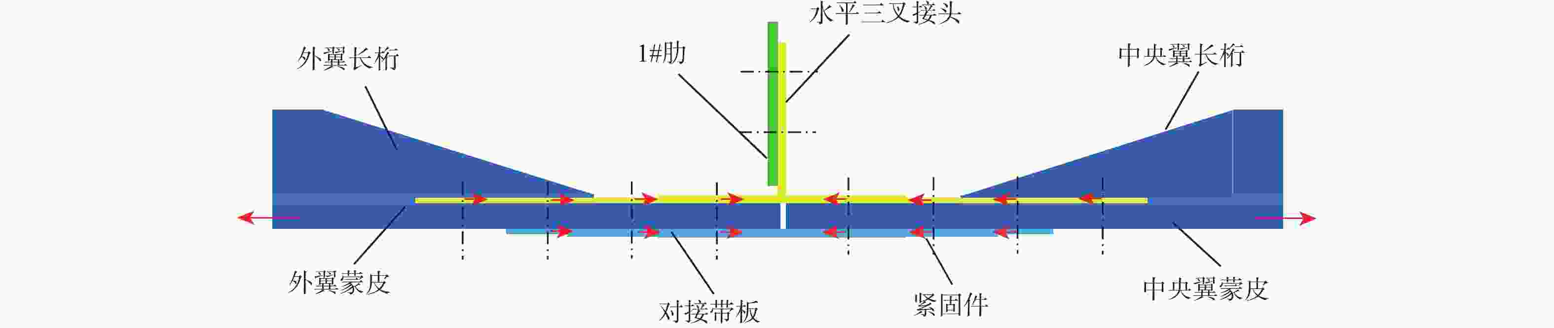
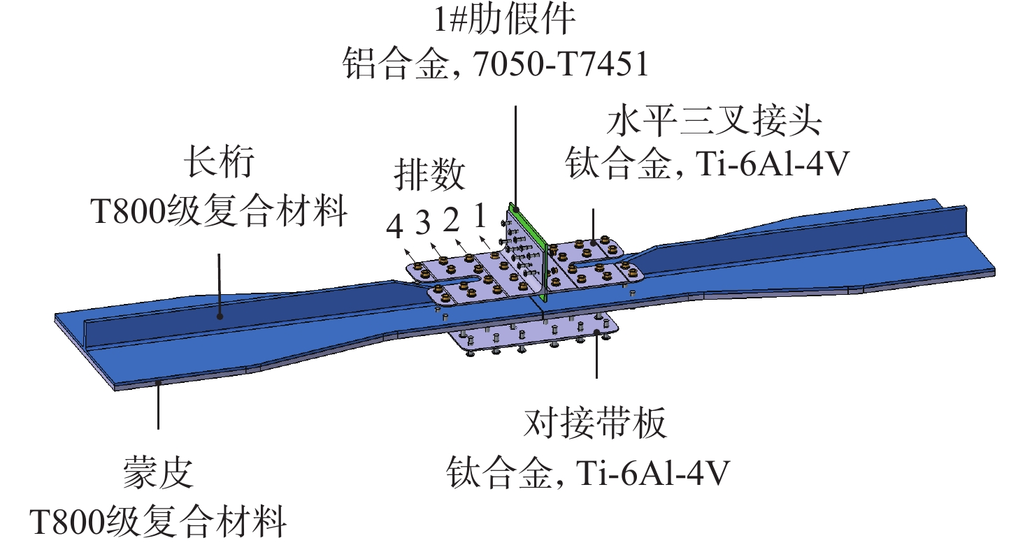
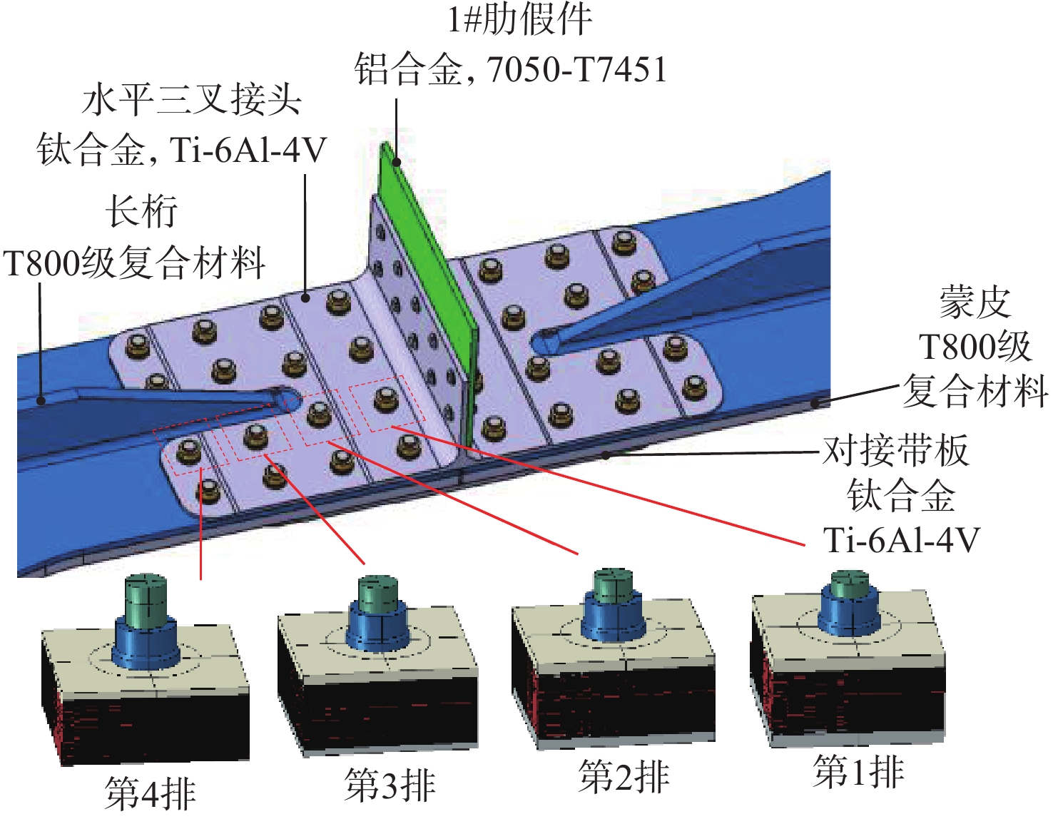
图 1 复合材料机翼翼根下壁板对接剖面
Figure 1. Cross section of composite wing root lower panel butt joint
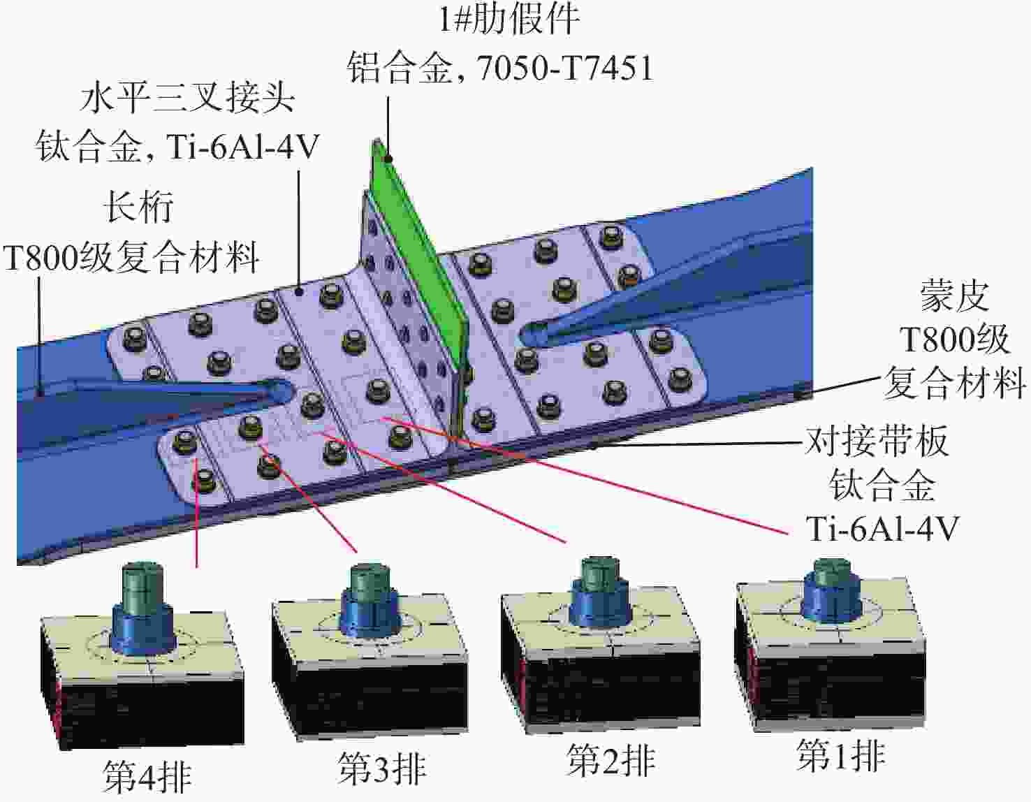
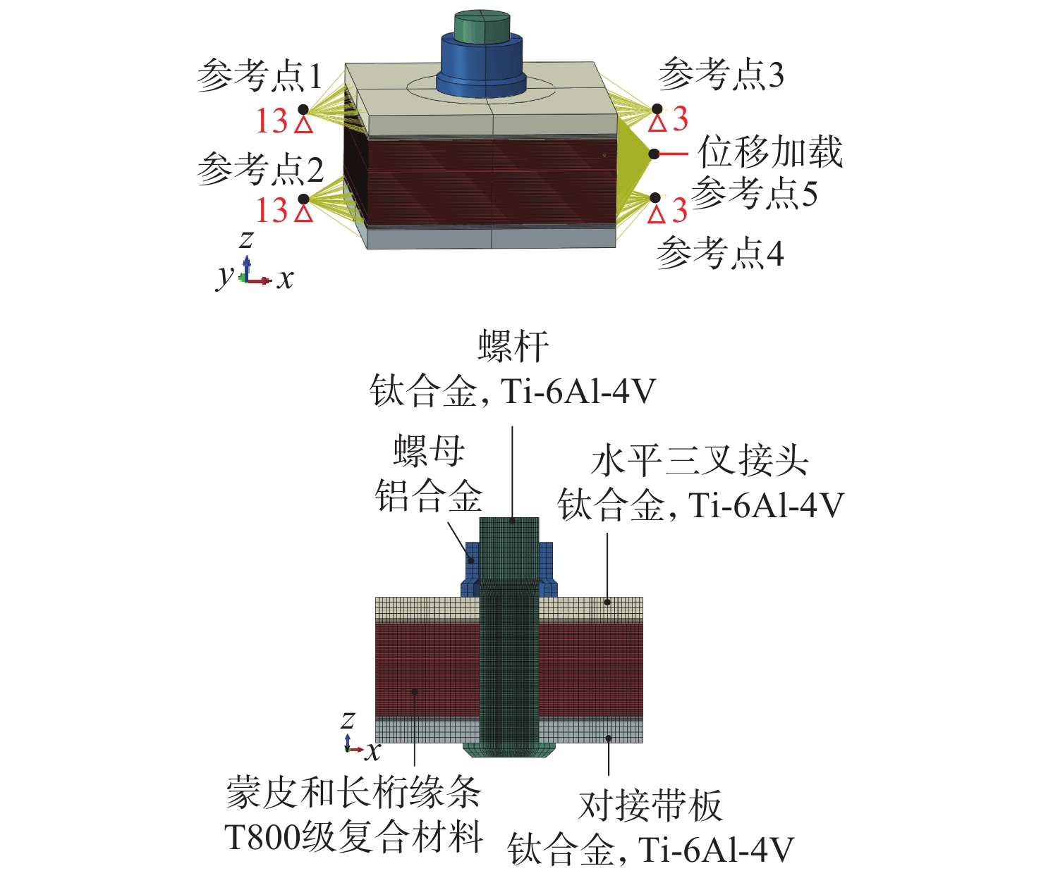
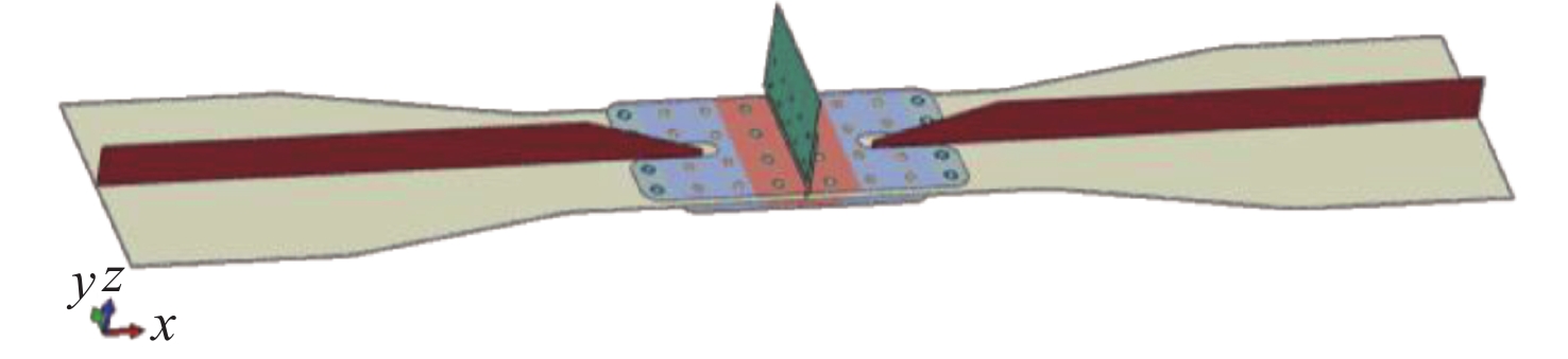
图 3 翼根长桁对接试验件子模型建模思路
Figure 3. Sub-model modeling method of wing root stringer joint specimen
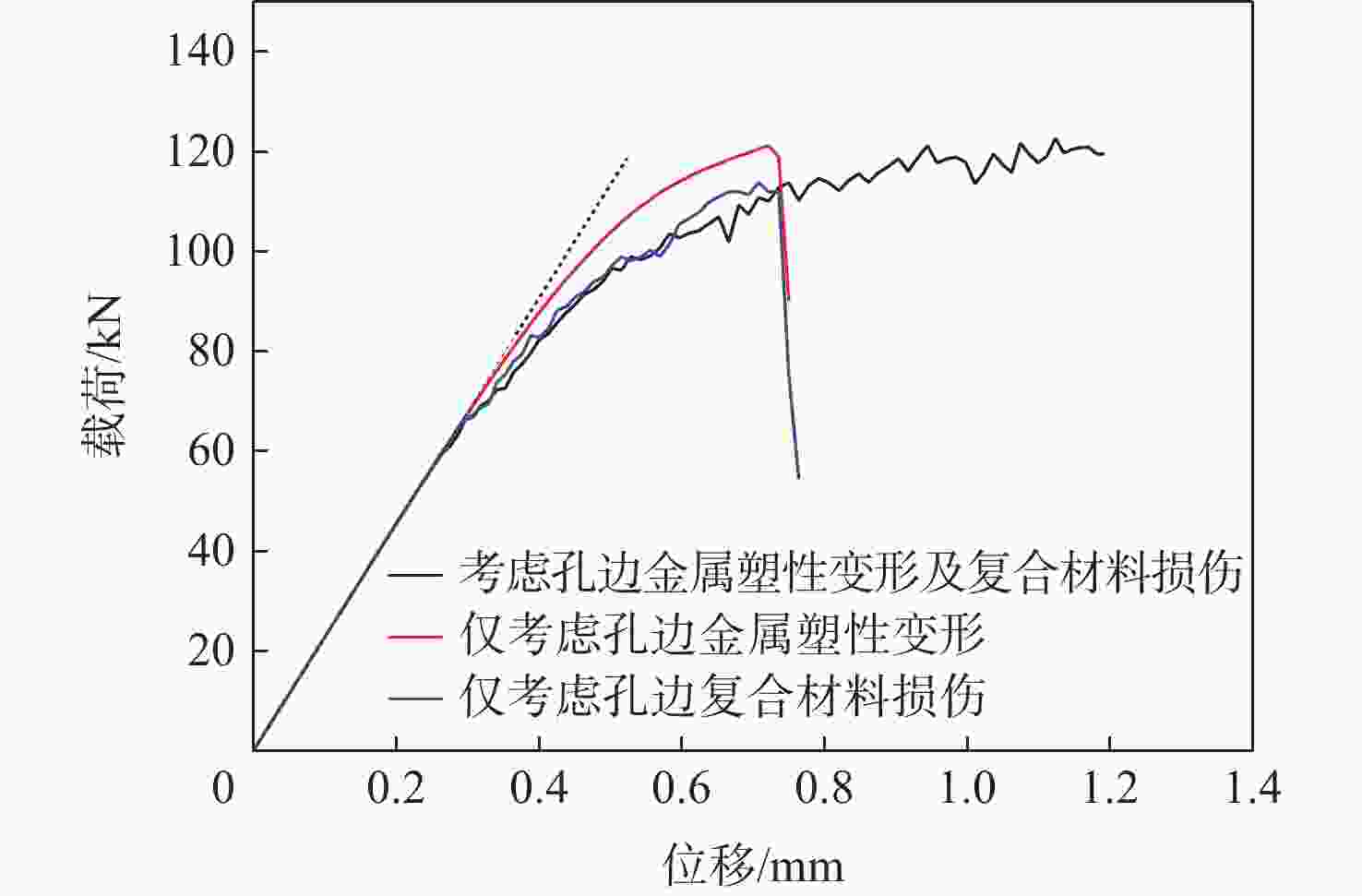
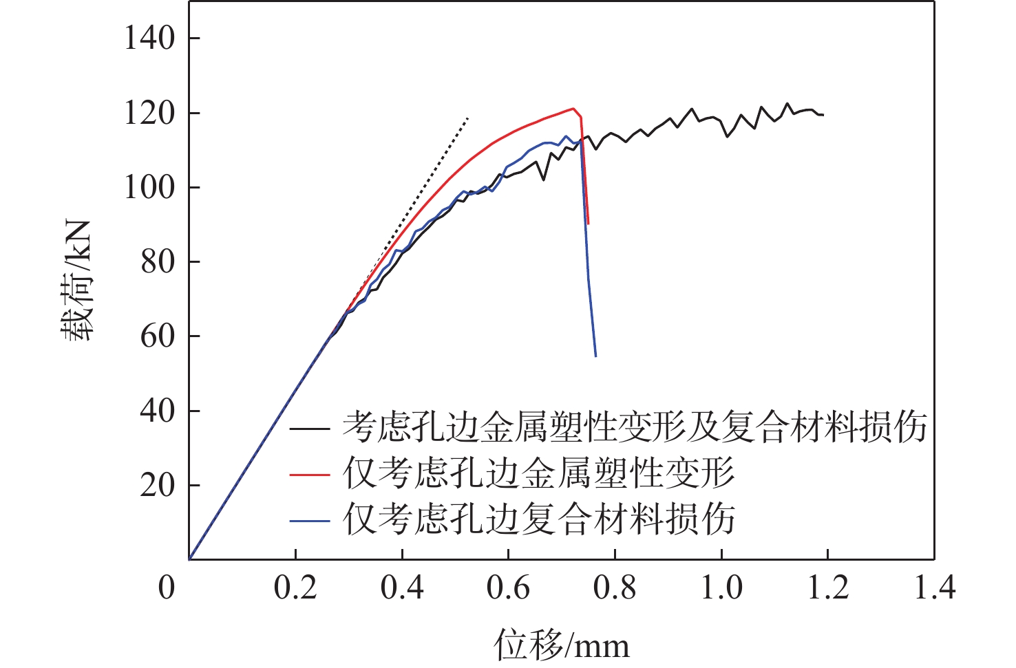
图 9 第1排子模型考虑不同损伤类型的载荷-位移曲线
Figure 9. Load-displacement curves of the 1st row sub-model considering different damage types
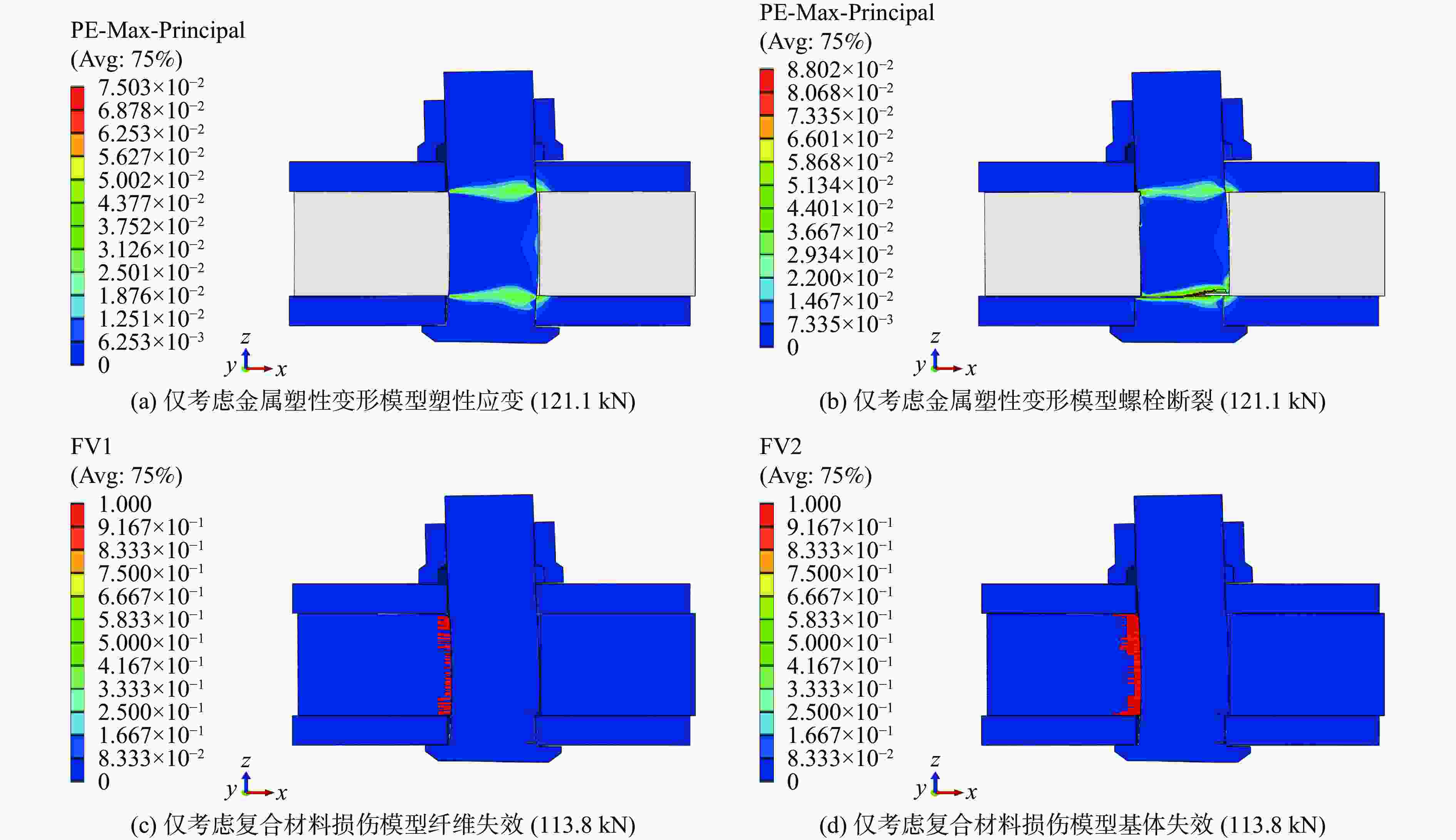
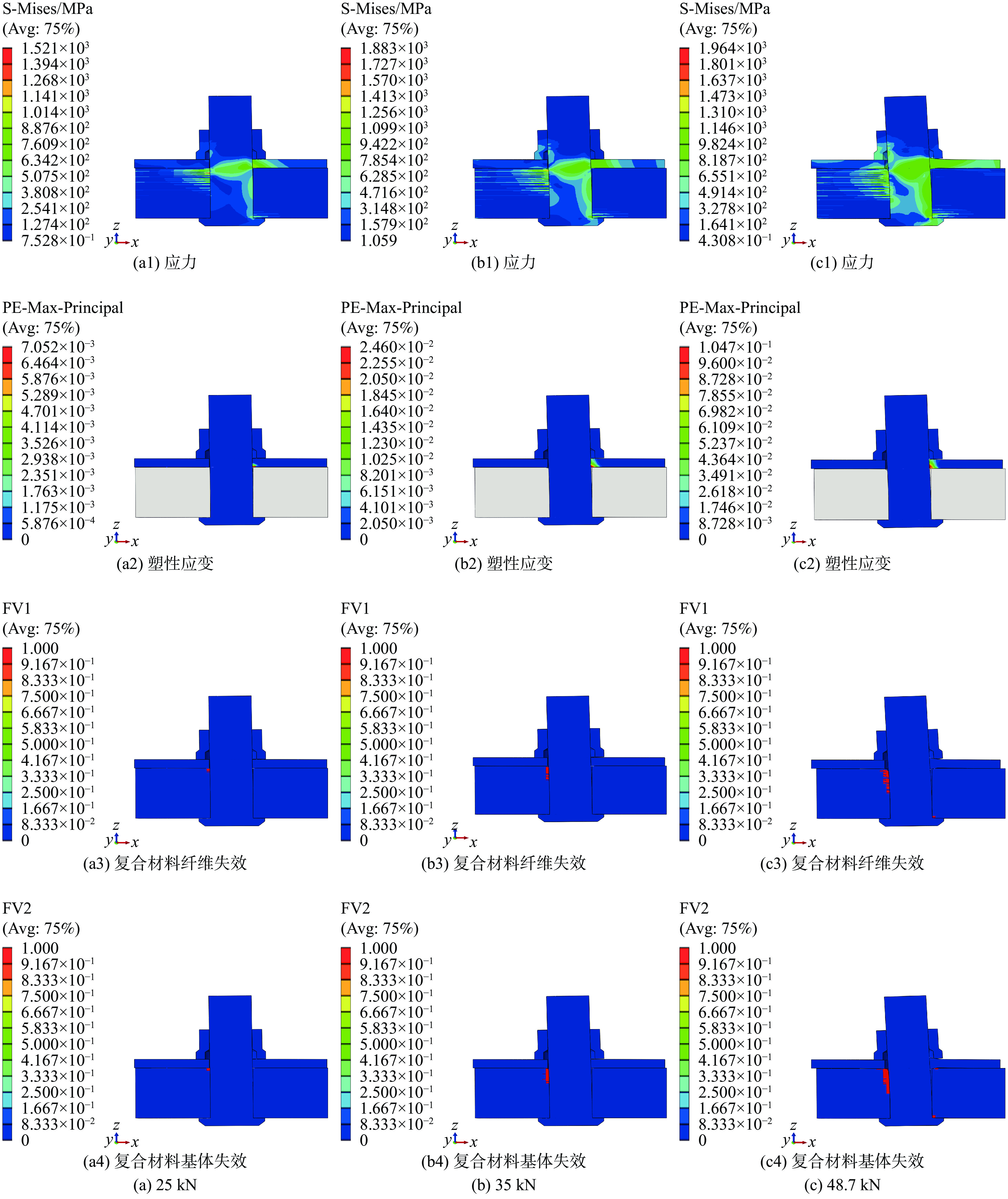
图 10 第1排连接考虑不同损伤类型子模型的破坏形式
Figure 10. Failure modes of the 1st row sub-model considering different damage types
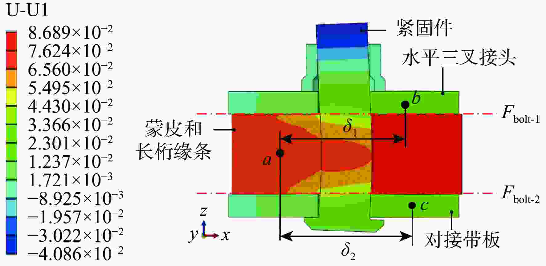
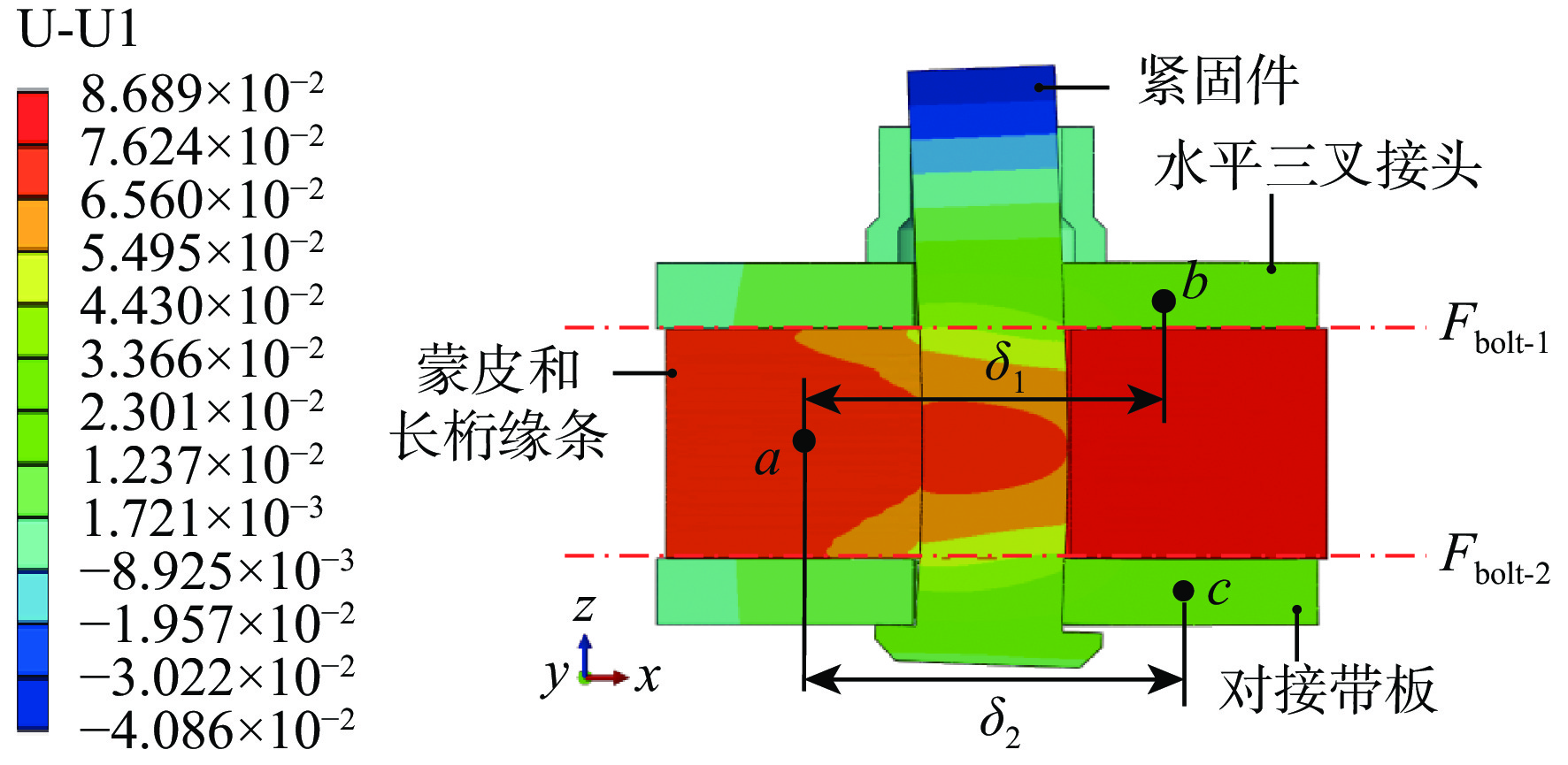
图 11 子模型连接刚度计算示意图
Figure 11. Schematic diagram of sub-model joint stiffness calculation
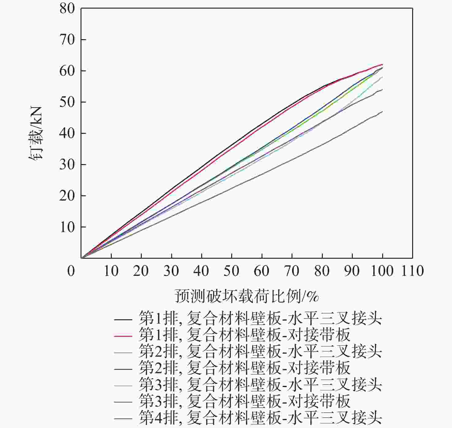
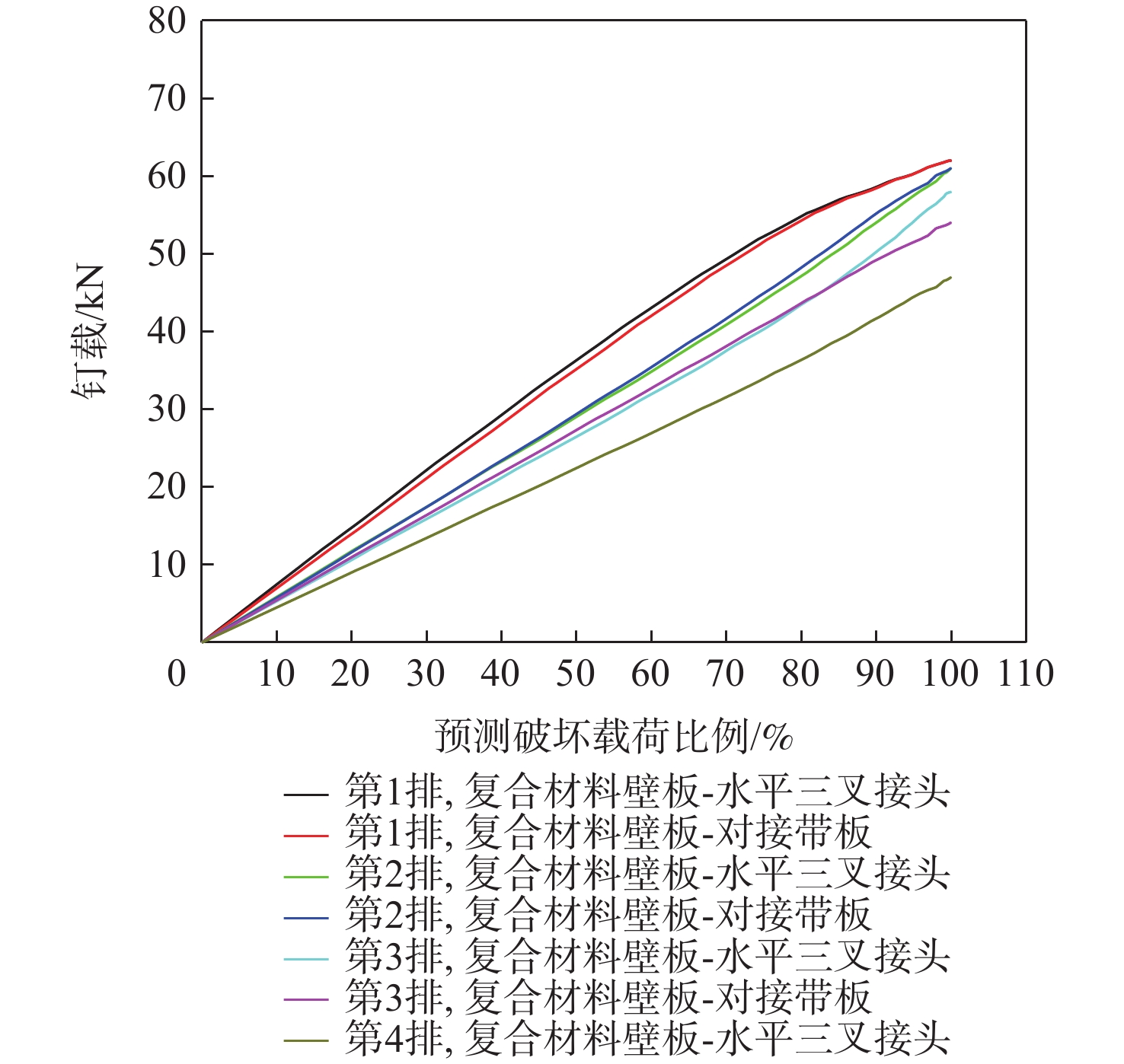
图 13 非线性连接刚度钉载计算结果
Figure 13. Bolt load calculation results using non-linear joint stiffness
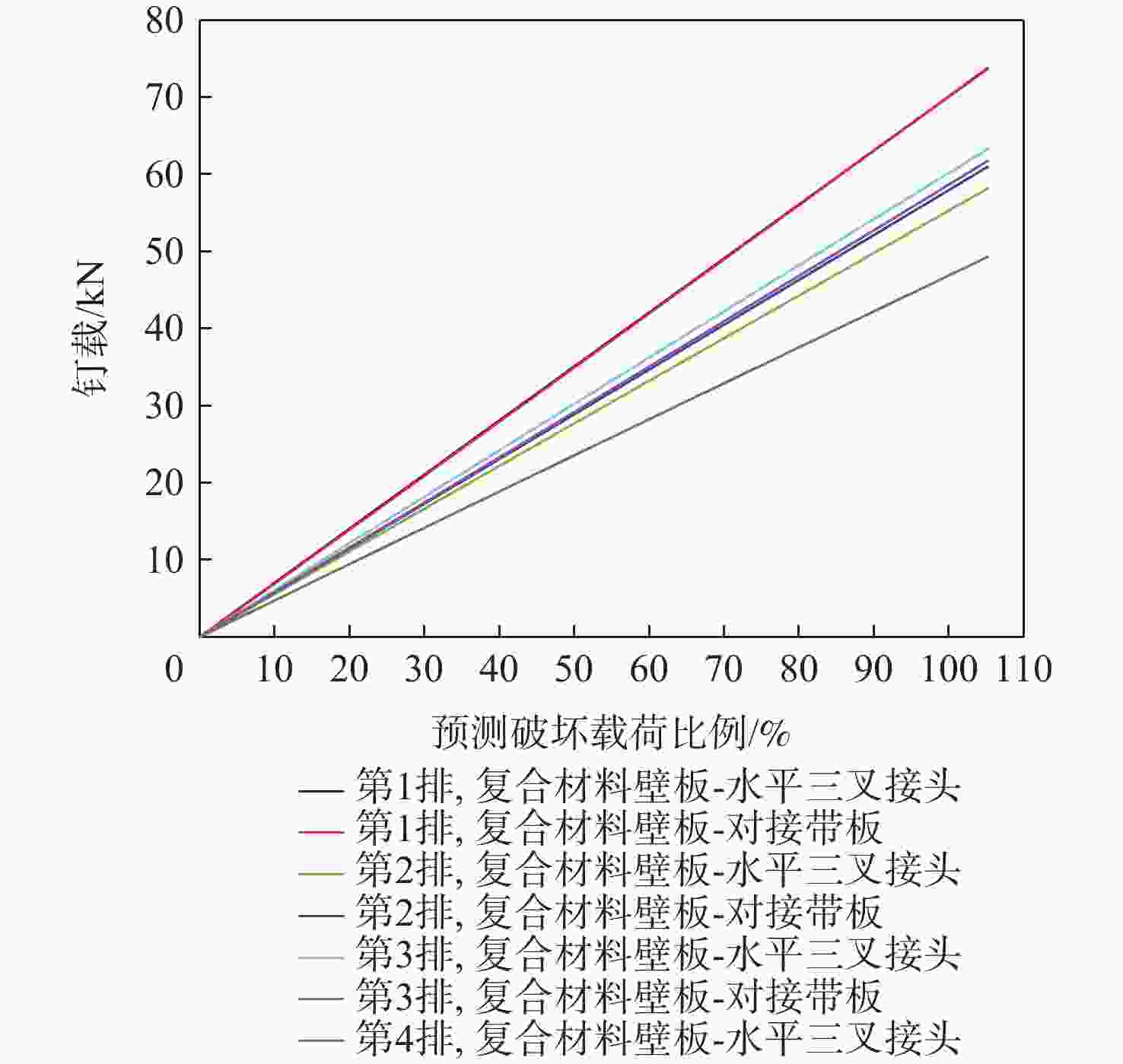
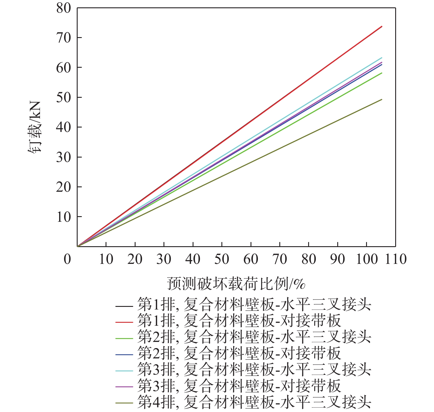
图 14 线性连接刚度钉载计算结果
Figure 14. Bolt load calculation results using linear joint stiffness
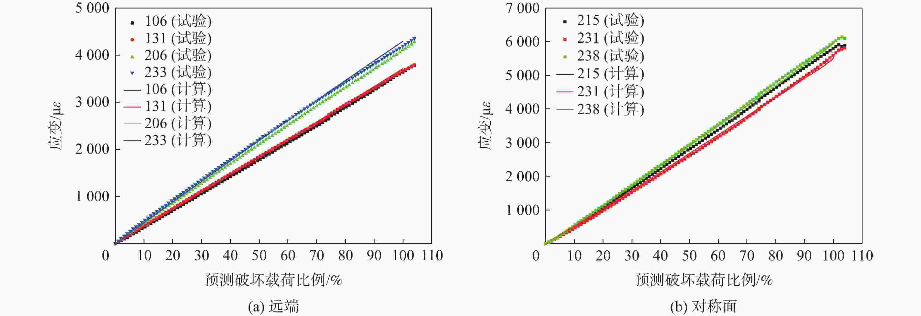
图 18 试验件远端和对称面处应变计算结果与试验结果对比
Figure 18. Comparison of calculated strain results with experimental results at location of far field and symmetry plane of specimen

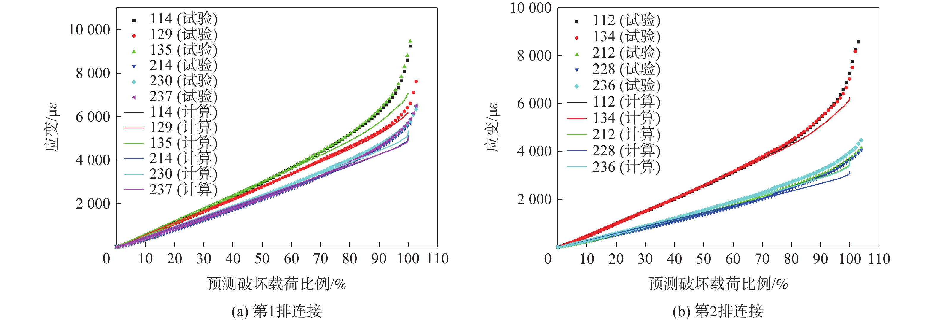
图 19 试验件第1排和第2排连接处应变计算结果与试验结果对比
Figure 19. Comparison of calculated strain results with experimental results at location of the 1st row joint and the 2nd row joint of specimen
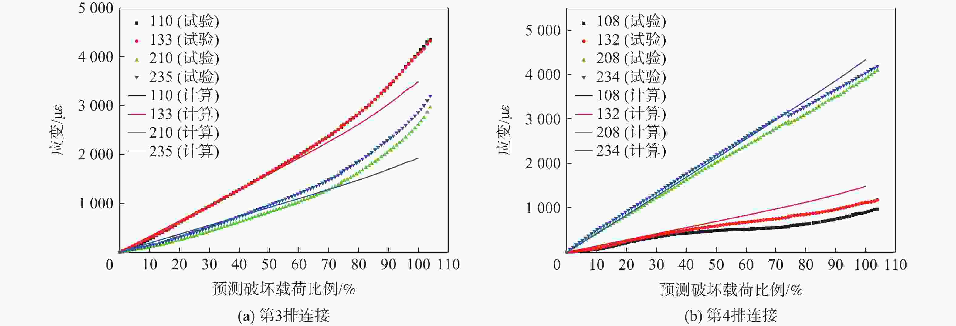
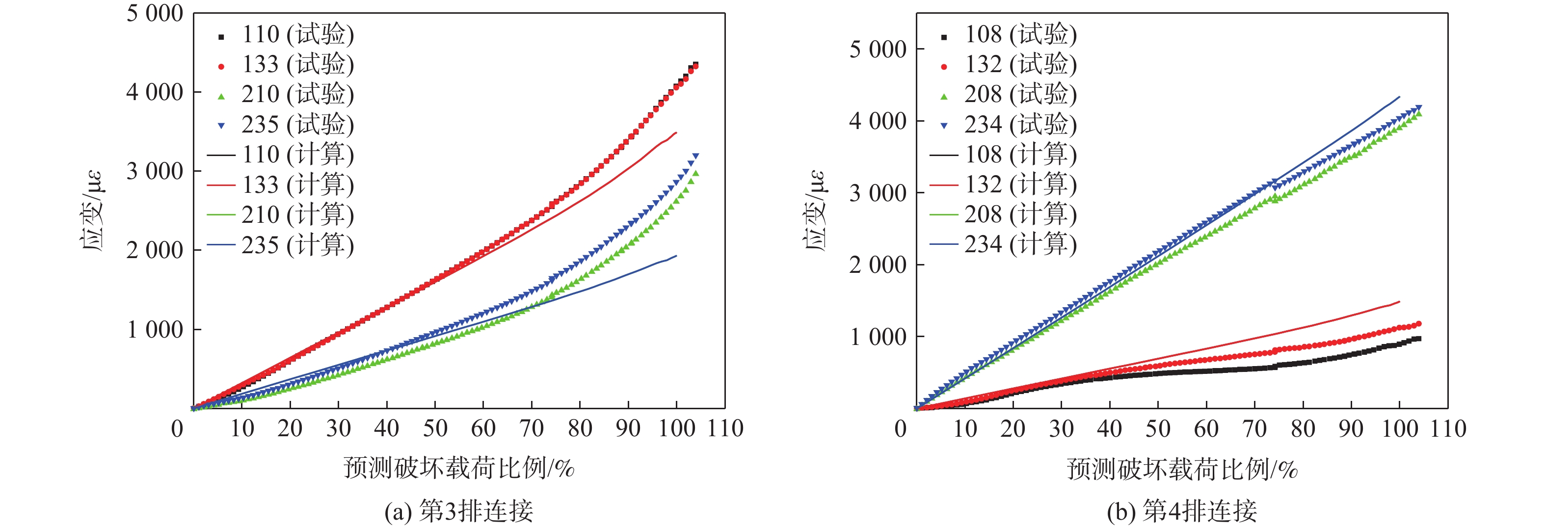
图 20 试验件第3排和第4排连接处应变计算结果与试验结果对比
Figure 20. Comparison of calculated strain results with experimental results at location of the 3rd row joint and the 4th row joint of specimen
材料 计算参数 数值 复合
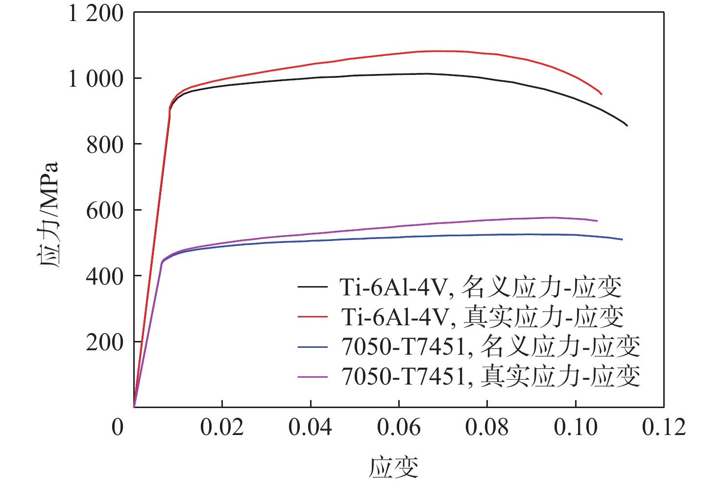
材料沿纤维方向弹性模量E11/GPa 163.5 垂直纤维方向弹性模量E22/GPa 9.00 面内剪切模量G12/GPa 4.14 面内泊松比ν12 0.319 厚度t/mm 0.191 单层0°拉伸强度/MPa 3071.0 单层0°压缩强度/MPa 1747.0 单层90°拉伸强度/MPa 88.0 单层90°压缩强度/MPa 271.0 单层面内剪切强度/MPa 131.0 Ti-6Al-4V 拉压平均弹性模量E/MPa 116522 剪切模量G/MPa 44816 泊松比ν 0.31 板材拉伸极限强度/MPa 931 板材剪切极限强度/MPa 545 紧固件拉伸极限强度/MPa 1103 紧固件剪切极限强度/MPa 655 7050-T7451 拉压平均弹性模量E/MPa 71016 剪切模量G/MPa 26890 泊松比ν 0.33 拉伸极限强度/MPa 510 剪切极限强度/MPa 290  下载: 导出CSV
表 2 复合材料损伤后性能退化方案
Table 2. Performance degradation scheme of composite material after damage
失效模式 退化方案 E11 E22 E33 G12 G13 G23 ν12 ν13 ν23 完好 1 1 1 1 1 1 1 1 1 纤维失效 0.01 1 1 0.01 0.01 1 0.01 0.01 1 基体失效 1 0.01 0.01 0.01 0.01 0.01 0.01 0.01 0.01 纤维失效+基体失效 0.01 0.01 0.01 0.01 0.01 0.01 0.01 0.01 0.01
下载: 导出CSV
-
[1] 杜善义, 关志东. 我国大型客机先进复合材料技术应对策略思考[J]. 复合材料学报, 2008, 25(1): 1-10. doi: 10.3321/j.issn:1000-3851.2008.01.001DU S Y, GUAN Z D. Strategic considerations for development of advanced composite technology for large commercial aircraft in China[J]. Acta Materiae Compositae Sinica, 2008, 25(1): 1-10(in Chinese). doi: 10.3321/j.issn:1000-3851.2008.01.001 [2] 谢鸣九. 复合材料连接技术[M]. 上海: 上海交通大学出版社, 2016: 129-235.XIE M J. Joints for composites materials[M]. Shanghai: Shanghai Jiao Tong University Press, 2016: 129-235(in Chinese). [3] HART-SMITH L J. Bonded-bolted composite joints[J]. Journal of Aircraft, 1985, 22(11): 993-1000. doi: 10.2514/3.45237 [4] GRAY P J, MCCARTHY C T. A highly efficient user-defined finite element for load distribution analysis of large-scale bolted composite structures[J]. Composites Science and Technology, 2011, 71(12): 1517-1527. [5] ZHANG F, HU Z D, GAO L M, et al. Investigation on in-plane shear behavior of large-size composite plates with multi-bolt joints[J]. Composite Structures, 2020, 232: 111553. doi: 10.1016/j.compstruct.2019.111553 [6] SASIKUMAR A, GUERRERO J M, QUINTANAS-COROMINAS A, et al. Numerical study to understand thermo-mechanical effects on a composite-aluminium hybrid bolted joint[J]. Composite Structures, 2021, 275: 114396. doi: 10.1016/j.compstruct.2021.114396 [7] 李玺, 李亚智, 磨承杰, 等. 基于连续损伤力学的复合材料多钉连接失效分析和试验研究[J]. 机械强度, 2022, 44(4): 911-920.LI X, LI Y Z, MO C J, et al. Failure analysis and experimental study of composite multi-pin connections based on continuum damage mechanics[J]. Journal of Mechanical Strength, 2022, 44(4): 911-920 (in Chinese). [8] 黄河源, 赵美英, 万小朋, 等. 一种复合材料螺栓连接结构非线性刚度模型及应用[J]. 西北工业大学学报, 2018, 36(1): 66-73. doi: 10.3969/j.issn.1000-2758.2018.01.010HUANG H Y, ZHAO M Y, WAN X P, et al. A composite bolted joints non-linear stiffness model and its application[J]. Journal of Northwestern Polytechnical University, 2018, 36(1): 66-73(in Chinese). doi: 10.3969/j.issn.1000-2758.2018.01.010 [9] 蔡启阳, 赵琪. 环境温度和间隙对复合材料-金属混合结构机械连接钉载分配的影响[J]. 复合材料学报, 2021, 38(12): 4228-4238.CAI Q Y, ZHAO Q. Effects of temperature and clearance fit on the load distribution of composite-metal hybrid structures[J]. Acta Materiae Compositae Sinica, 2021, 38(12): 4228-4238(in Chinese). [10] 张岐良, 曹增强. 复合材料螺接性能的影响因素研究[J]. 航空学报, 2012, 33(4): 755-762.ZHANG Q L, CAO Z Q. Study on factors influencing the performance of composite bolted connections[J]. Acta Aeronautica et Astronautica Sinica, 2012, 33(4): 755-762(in Chinese). [11] 雷凯, 王彬文, 成竹, 等. 飞机多钉壁板混合结构热应力分析与验证[J]. 应用力学学报, 2023, 40(1): 40-47. doi: 10.11776/j.issn.1000-4939.2023.01.006LEI K, WANG B W, CHENG Z, et al. Thermal stress analysis and verification of aircraft multi-bolt hybrid panel structure[J]. Chinese Journal of Applied Mechanics, 2023, 40(1): 40-47(in Chinese). doi: 10.11776/j.issn.1000-4939.2023.01.006 [12] 贾宝惠, 方嘉晨, 武涛, 等. 预紧力影响下的复合材料螺接连接件失效安全性分析[J]. 机械科学与技术, 2025, 44(7): 1290-1300.JIA B H, FANG J C, WU T, et al. Failure safety analysis of composite screw connection under the influence of pre-tightening force[J]. Mechanical Science and Technology for Aerospace Engineering, 2025, 44(7): 1290-1300(in Chinese). [13] 汤平, 李星. 插入式机翼下壁板对接附加弯矩研究[J]. 航空学报, 2019, 40(2): 522436.TANG P, LI X. Additional bending moment in lower panel butt-joint of inserted wing[J]. Acta Aeronautica et Astronautica Sinica, 2019, 40(2): 522436(in Chinese). [14] 高阳. 某型飞机中央翼关键连接区混杂结构试验仿真与分析[D]. 南京: 南京麻豆精品秘 国产传媒, 2020: 19-20.GAO Y. Experimental simulation and analysis of hybrid structure in key connection area of central wing of an aircraft[D]. Nanjing: Nanjing University of Aeronautics and Astronautics, 2020: 19-20(in Chinese). [15] RICE R C, JACKSON J, BAKUCKAS J, et al. Metallic materials properties development and standardization (MMPDS)[M]. Washington, D. C. : U. S. Department of Transportation Federal Aviation Administration, 2003. [16] ASTM. Standard test method for bearing response of polymer matrix composite laminates: ASTM D5961/D5961M-23[S]. Philadelphia: ASTM International, 2017: 1-31. [17] HUTH H. Influence of fastener flexibility on the prediction of load transfer and fatigue life for multiple-row joints[C]//Proceedings of the Fatigue in Mechanically Fastened Composite and Metallic Joints. Philadelphia: ASTM, 1986: 221-250. -

 下载:
下载:


 点击查看大图

计量
- 文章访问数: 198
- HTML全文浏览量: 55
- PDF下载量: 5
- 被引次数: 0
